
![]()
When 'Dandy' (NKR31525) arrived back in England
it was immediately obvious that there was a problem with the engine cooling
system. After the engine had been running for a while the radiator header
tank was too hot to touch whilst the bottom tank remained cold. The immediate
assumption was that the tubes within the radiator core were blocked.
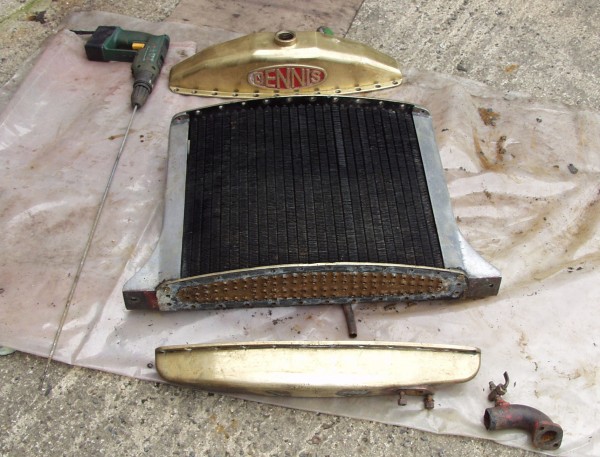
When the radiator was taken apart it was apparent that Dandy must have spent his time pumping Zambesi river mud or the like, as every tube was blocked solid. (During pumping operations with the main 250 gallon per minute fire fighting water pump, a fraction of the pumped water is fed into the engine cooling circuit to prevent the engine from overheating. Filtration of this water is only nominal, by a coarse metal gauze filter). A 6mm drill welded onto a length of rod, held in an electric drill proved to be the ideal tool for cleaning out the radiator tubes. When everything was re-assembled there was the expectation that all would be fine. However the lack of water circulation still existed.
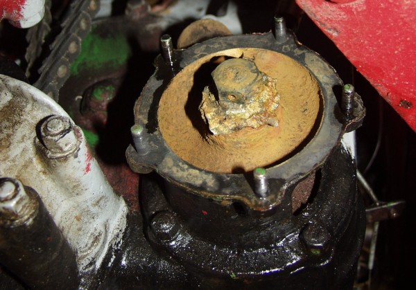
On turning our attention to the water pump, the problem became obvious. 70 years of use had reduced the engine water pump impeller to just a stub. Nick Grenside of Dennis found the original factory drawing for me, and this was translated into a 3D CAD drawing using a system called 'Mastercam'.
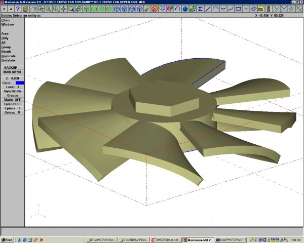
From the Mastercam drawing the toolpaths for a ball nose milling cutter are developed so that the impeller may be cut out from a solid brass billet.
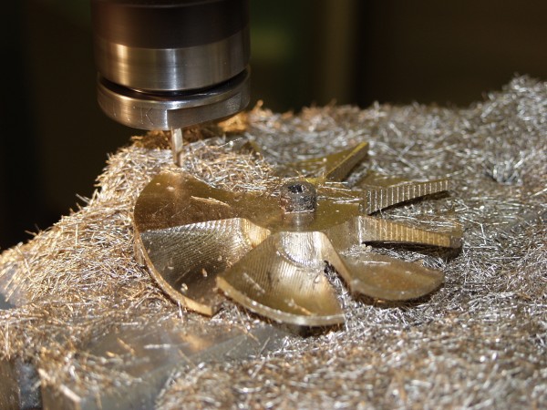
In this photograph the front side of the impeller has already been machined and most of the reverse side too. Only one more segment now has to be cut. The cutter follows the contour of the blade in tiny incremental steps, so that the resultant curved 3 dimensional surface is almost smooth.
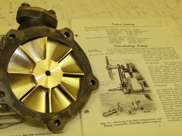
The finished impeller sits inside the water pump housing. Dandy now runs as cool as a cucumber!
![]()